Yes, it happens. A project file is started, then more data comes in, and the survey finally arrives, and it turns out that what you’ve started designing in response to isn’t quite oriented how you thought. Or, the team does a shadow study in response to plan check comments, and things need to not just move, but… rotate. Well into the design. And the documentation.
It happens.
So, what’s a team to do? There are several options:
a) Grab everything, and rotate the building. [yeah, I didn’t think so…]
or
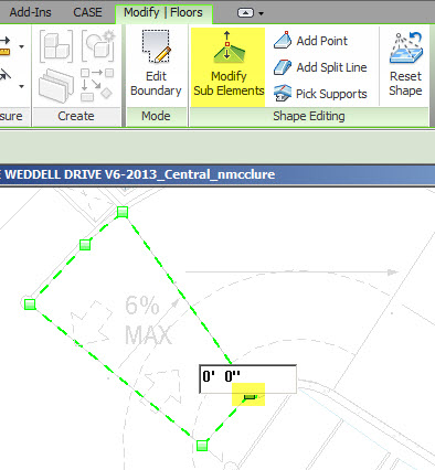
b) Rotate project North, (& reset your angle to True North)
c) Rotate the site and any north referencing annotations and be done with it (see notes at end of the post as to why this wasn’t opted for).
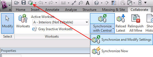
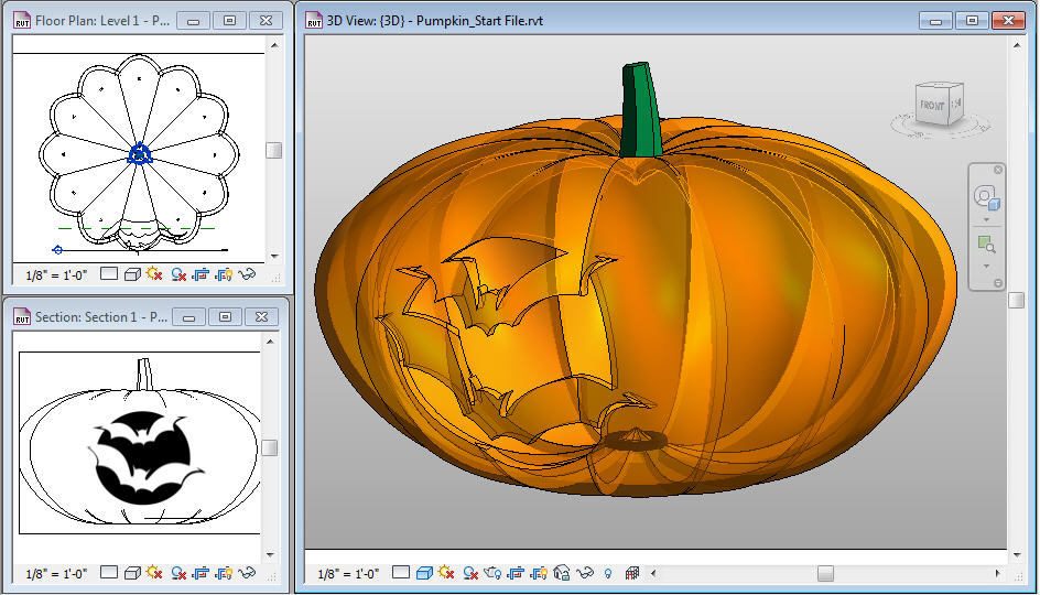
As you can guess, the team opted for b) Rotating True North. Here’s a summary of what we encountered (and are still sorting through):
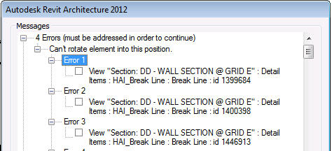
Things that blocked the rotation:
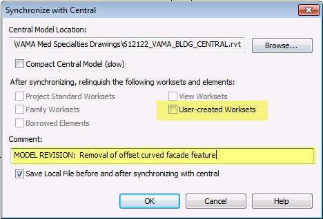
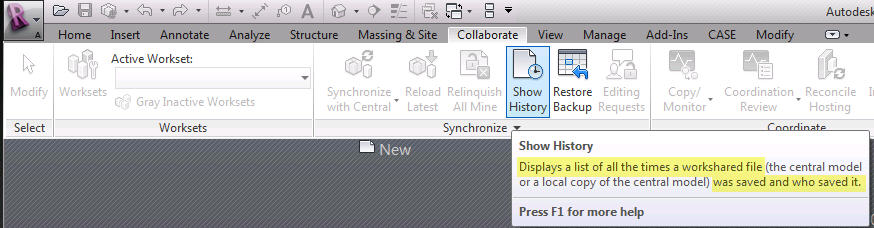
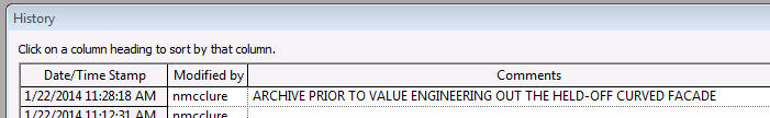
- Detail components and symbols placed on vertical views (sections, elevations). Yes, all of them. We were at a phase transition, so we archived, then blew out these elements (from the Project Browser, selected all instances in the project, delete) You have to do it one family at a time, but it was still much faster than opening views, selecting, filtering and deleting. We lost some things from horizontal views (graphic scales and break lines, mostly) but it was still the more efficient choice. NOTE: Since we archived, we figured we could cut/paste 2D components from the archive to the adjusted views, which we did.
- Some element relationships. Not sure what, probably alignments formed between graphical and model elements.
Note, determining what was blocking the rotation was trial and error at first, as Revit would pop up a warnings dialog, and allow you to delete the offending elements. But then it would choke and not complete the action, only allowing a cancel of the attempted rotation. After several of these attempts, we stopped, created and ran tests on a small dummy project to see what caused the choke.
Notable, not ALL 2D elements on views triggered warnings (text leaders, dim strings and room tags were fine). So by testing and narrowing down, we were saved from the initial impulse of deleting ALL 2D elements from vertical views.
What Failed to Rotate:
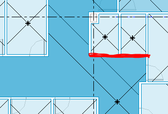
We hadn’t expected things on horizontal views to be affected, but they were. The test file exercise checked on the things we worried about most – orientation of all the interior elevations that had been created, and already placed on sheets. Those adjusted fine. We (kinda/sorta) understood why the 2D elements on vertical views caused a ruckus, but found that several (not all) 2D elements on horizontal views were exempted from the rotation, or even more bizarrely, some rotated, some didn’t, and some rotated in the opposite direction. Go figure.
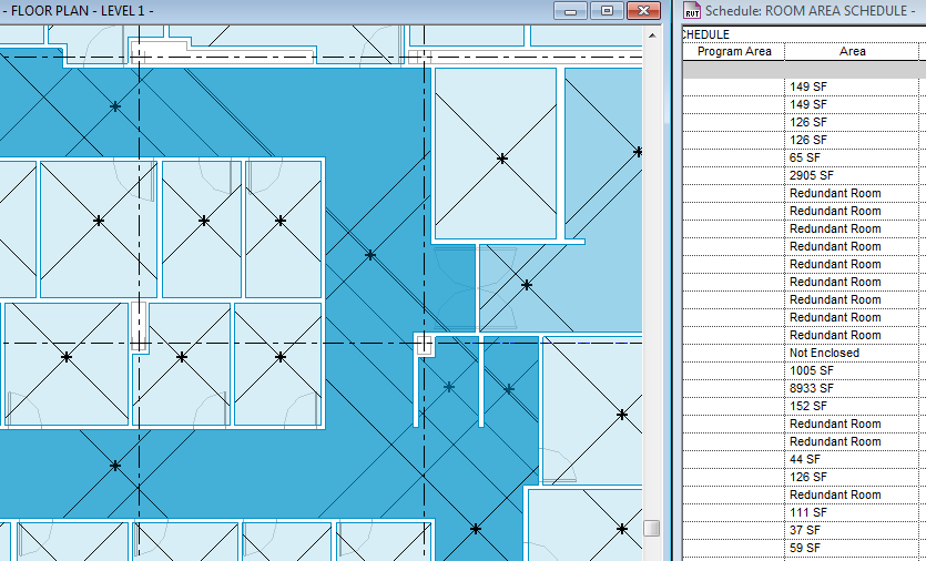
A few of the Room elements reacted strangely, too. by being shifted from their original location to overlap another region of the model. We suspected that rooms bound by room boundary lines would be the ones that got dislodged, but it wasn’t them – it was fully wall enclosed rooms, for no known reason.
Callouts from plans rotated along with the the model, but the resulting views placed on sheets were suddenly not oriented. We’re still scratching our heads over that one. These were true callouts, not referenced callouts, which I anticipated would not correlate to the original callout.


