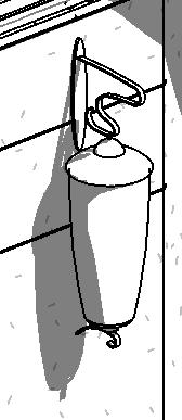
First off – not EVERYTHING in a virtual 3D model needs to be in 3D.
This is an important concept to emphasize, as the first impulse of a team is that everything will be 3D, and that can be overwhelming (both in terms of content creation needs, but also potentially in file size management), particularly in projects with high customization (high-end residence, restaurants, etc).
Once a team realizes that not everything will be modeled, some users default to basic drafting (detail lines) to represent visually complex items, and that also needs to be reevaluated for efficiency and output impact.
My recommended strategic process of determining what needs to be 3D and what does NOT, and how those non-3D elements should be SMARTLY created, follows this analysis:
a) Will the element need to scheduled / counted / assigned data?
b) What key views will the element be referenced in? ie: Overall 3D? Interior perspectives? Interior elevations? Floor/Ceiling plans?
c) Are there manufacturer resources that could be leveraged? ie: downloadable CAD elevations, etc.
d) Is there a critical spatial impact that will be assessed for clash detection?
It needs to be Scheduled
This key requirement rules out detail line drafting, and defines that the element should be created as a component family (.rfa). This does NOT however, require the component to be fully 3D modeled (see 2.5D Families).
*In place families can be scheduled, but are more difficult to coordinate with other components used in the model.
Views Element is Documented In
 If the main views the element will be seen in are 3D/perspective views, then it should be modeled in 3D. Consider what plot scale those views will be presented in, and consider reducing the complexity of the geometry accordingly.
If the views will be only plans, then the geometry can be omitted from the family, and model or symbolic lines used in floor/ceiling plan views (a strictly 2D family).
 This is especially efficient for very repetitive elements, such as recessed light fixtures, which are only represented in RCPs, but need to be scheduled for fixture counts, etc.
If the views the element will be represented in are BOTH floor/ceiling views and interior elevations, yet not involving 3D views, the most efficient creation route is a 2.5D family – 2D linework in 3 dimensions.
2.5D Families
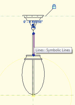
Component families do NOT have to involve geometry. Complex forms that will be represented only in 2D views in your documentation can be efficiently created using 2D linework in 3 views: plan, front elevation and side elevation.

Gather your resources
Many manufacturers provide downloadable CAD files of their products in both plan and elevation views. These can be leveraged to quickly create dimensionally accurate 2.5D families in Revit. Insert the CAD elevation into both the front/back AND left/right elevations in the family editor, and pick/draft the linework. Delete the embeded CAD file prior to saving/inserting into your project environment.
Parametric 2.5D
Omitting 3D geometry in the component family does NOT preclude creating smart, parametric families. Simply associate your key linework the same way you would for 3D geometries, focusing on the endpoints of lines, rather than planar surfaces of geometry.
Critical Clearance Issues
Some elements need critical clearances to ‘trigger’ the automated clash detection process in Revit. A simple geometric form that is set to an ‘invisible’ material can accomplish this, with a custom subcategory to set the ‘clearance zone’ edges to dashed lines in plan/elevations.


Pingback: Trackback