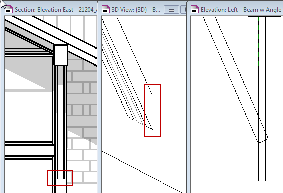
Users often complain about ‘missing lines’ where complex assemblies overlap/embed into each other:
 The easiest resolution for this is to use the Join Geometry tool, and select the two elements that overlap, however if the elements are (as in this case) nested within the family that you are trying to Join, this does not resolve the issue. The adjustment must be made in the original element family:
 RESOLUTION:
Add a VOID into the family that ‘clips’ off the portion that would be embedded into the project element. This creates a ‘hard line’ cut edge of the element that appears in the project environment. The reason for the space, as seen in the section view, is that the wall-based family is created on a default host wall, which lacks any finish material definition:
 The user needs to anticipate the depth of finish layers, and plan that offset into the component family. Alas, there is no way to have the family ‘read’ the project host data and adjust automatically.
TIP: When creating wall-based component families, adjust the template default wall to the thickness anticipated in the project(s). This is especially helpful with complex components that have geometry that insets into its host.


The reporting parameter concept was introduced to help determine the nature of a host from within the family. In your example, it may be possible to associate a reporting parameter with the wall thickness. Then you could determine through a formula, either mathematical, logical or both, how to adjust the end of the other elements.
The often sited example (for reporting parameters) is evaluating wall thickness for door frame adjustments where walls that are thick enough can use a 8″ frame and thinner walls must use 4″ frames.
Hi Steve – thanks for the note! I’ll look into that – I’ve had inconsistent success with aligning to ‘face of wall’ reference planes, which supposedly adjust for project overall wall thickness.
Pingback: Trackback
Pingback: Trackback