Nesting Shared Elements

Combining a bunch of stuff into a single family (nesting) makes modeling more efficient, and can be less of a processing hit than groups – but there are some things to consider – specifically, if the nested elements should be SHARED.

By default, component families are not set to be shared. This setting is in the general parameters of each family.

WhNested Familyen not shared, the nested element is not recognized as separate from the overall family it is placed in, and only the entire collection can be selected, tagged or scheduled.

A decision should be made UP FRONT on if the individual elements of a nested family need to be tagged/scheduled. If this is required, each nested family must be SHARED.

element SHAREDThis is a modification you want to do sooner rather than later, as when the modified element is reloaded into the respective multi-element family, and then that parent family is loaded into the project, the other nested elements in the other multi-element families do NOT update automatically. This can result in differing appearance/behavior across what you THINK is the same element. Chaos ensues.

UPDATED shared element
To update across the project, each nested family needs to have the updated sub-component reloaded into it, then that nested family reloaded into the project.
As an added complication, changing the SHARED parameter requires overwriting WITH parameter overrides, which could alter numerous instance settings applied across the project.
shared sub-component
Now, it seems like the best thing would be to go ahead and SHARE everything nested – but the downside to that is reloading updates to individual elements is MUCH more processing intensive. This can be a real workflow bog-down if many of those elements will not ever need to be individually scheduled.  SO – the lesson here is to decide what will need tagging/scheduling, and share ONLY those elements.
Posted in BIM/Revit | Tagged , , | 5 Comments

Project Start Up – Site File

Although a Revit file can be a complete site, I HIGHLY RECOMMEND teams model the SITE separately from the BUILDING.
Here’s why:

1) Buildings are modeled in PROJECT NORTH by default. This makes for more accurate models/data, and supports the majority of the documentation layout.
2) SITES are often created directly from CAD/Civil documents, which are generally TRUE NORTH. Separate SITE and BLDG files make this easier to manage.
3) A separate BLDG allows various siting/positioning studies to be easily and quickly performed, to evaluate daylighting and sunshadows. It is VERY difficult and messy to attempt this when the file is all together as one.
4) Processing for larger site projects is much more efficient with separate SITE and BLDG models, using worksets and unloading the linked file when not being focused on.

Setting up the files:
Revit BasePointIMPORTANT: The Project Base Point is Revit’s “ORIGIN” – this cannot be changed. If you want the Revit origin to be located elsewhere in the future, the MODEL must be moved around this stationary point. Due to all the inherent vertical workplane relationships within the model, picking it up and moving it can be VERY MESSY and time consuming, and can break a lot of the model. A thoughtful decision about where to begin modeling relative to this fixed-origin is extremely important!

TO USE THE CAD ORIGIN (OR NOT):
IF the Civil/CAD resource for the site has a workable origin (locating the final project extents wholly within a 20′ diameter area) the CAD file can be linked in ORIGIN-to-ORIGIN to keep those points the same. NOTE: This does not resolve the rotational difference between PROJECT and TRUE North, which must still be manually set initially.

If the CAD origin does NOT work for direct use in Revit, I recommend the team select a VISUAL/KNOWN POINT (Property Line, or other easily referenced and static point). Link the CAD file in CENTER-to-CENTER (which Revit will default to, if the ORIGIN-to-ORIGIN is not viable), and MANUALLY move the CAD link to position the desired Reference Point to the Revit Project Base Point. Once positioned, PIN the CAD file to prevent accidental moving.
NOTE: selecting a visual point is recommended to facilitate exporting DWG backgrounds, and having a visual marker to assist with coordinating positioning across files without a shared origin.

STARTING WITHOUT A CIVIL BACKGROUND:
Often, a design team does not have any site/civil resources before beginning preliminary design. (Again, this is a strong reason for modeling the BLDG separate from the SITE).
In this case, start the BLDG file first, and model around the Revit Project Base Point, setting it to be a VISUAL/KNOWN POINT (Property Line, or corner of (E) building, or at the very least, the intersection of primary grids (A & 1). DO NOT leave the Base Point position to be arbitrary! This would become a real pain in the future, believe me.

COORDINATING WITH CAD ORIGIN:
This applies when the Revit model has not been able to coordinate to a CAD origin BEFORE developing the model. While this process is not required, it does make for much more convenient exports of CAD backgrounds from the Revit model that a consultant can xref in ‘Origin-to-Origin’ and not have to manually position things.

The prep work:

a) Create a line in the CAD file from 0,0,0 to a visually identifiable point (in this example, it is to the corner of an existing building footprint in the CAD file, which is also a known point in the Revit model)
b) WBLOCK that line referencing the 0,0,0 origin.
c) insert/link it into the Revit model, and rotate it to the delta of Project/True north
d) move the line end to the visually identifiable point.
e) PIN IT IN PLACE.

Set the Survey Point:

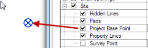
a) In a Level 1 ( 0′-0″) plan view, turn on the visibility of the Survey Point (VG: Site subcategory)
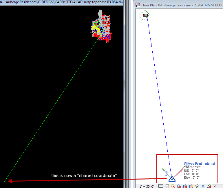
b) UNCLIP (the paperclip symbol) and MOVE the Survey point to the CAD origin end of the reference line
c) Using Manage > Specify Coordinates at a Point, set the Survey Point to 0, 0, 0.
d) RECLIP and PIN the Survey Point (this prevents accidental movement)
CAD Origin to Revit

Export a background view to CAD:
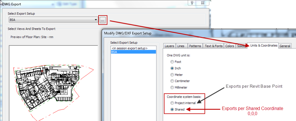
a) R > Export > CAD formats > DWG
b) Select the “…” button beside the Select Export Setup, and under the Units & Coordinates tab, select SHARED
c) proceed with export process.
Export via Shared Coordinate
RESULT:
DWG created will have it’s CAD origin set to the 0,0,0 point, AND include the true/project north rotation already applied (this assumes the True North rotation was already set in the Revit file – if not, the export will be to the Revit Project North orientation)
Exported PN to TN

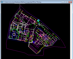
Revit view was Project North —> Exported via Shared Coordinates and result is CAD origin at 0,0,0, with True North rotation applied:

Posted in BIM/Revit | Tagged , , , | 3 Comments

Happy Easter!

I like my holidays secular, but will still indulge in a tradition or two – this is my second year making Ukrainian style Pysanky Eggs. Raw eggs are drawn on with melted wax using a special funnel-tip pen, and then dyed in various colors into a multi-layered pattern. They are time consuming, to say the least. But also quite fun, once you get past the first time you singe your fingertips in the hot wax.

Pysanky eggs

Posted in PublicArt | 2 Comments

Protected: Customizing Keynotes

This content is password protected. To view it please enter your password below:

Posted in BIM/Revit | Tagged , , , , | Comments Off on Protected: Customizing Keynotes

T.I. Test Fit Guidelines

Test fit requests often precede actual T.I. contracts, and are typically a very basic per-square-footage fee. As such, budgets rarely allow for 3D build-out of existing spaces, and the goal is primarily to get area summaries and office/workstation counts against the tenant’s programmatic goals.
Here are guidelines to creating Test Fit models within the budget:

Leverage the CAD background:
Most building owners have legacy CAD files of their building stock, hopefully up-to-date. Use as much as possible directly printed as backgrounds to the modeled Proposed New Work

  • Link in the CAD file. Assign to it’s own workset, and PIN it in place.
  • QUERY the CAD file and hide any layers that are not relevant (or overly graphic) to your intended deliverables.
  • Set visible CAD layers to black solid linework through the VG panel.
  • QueryCADlayers
    handdrawn plan

    NOTE: Even handdrawn plans can be used as backgrounds – insert the image and scale using a known dimension (typical 3′-0″ door, for example).

    AreaOfWork-Floors
    Use FLOORS to mask the existing CAD layout:
    Use a floor to both calculate the Area of Work, and to cover over CAD linework of existing layout. Use subset floors to define ‘zones’ if needed.
    AreaOfWork-Rounding

    Use Floor tags (TI Area of Work or TI Program Area) to list overall/subarea square footage. NOTE: The tags require manually typing in the area, to ’round up/down’ to an appropriate whole unit.

    ActiveDesignOption

    Create Design Options:
    Create a TEST FIT set, and create the number of Options you anticipate evaluating (you can add/delete later, if needed).
    Create elements CONSISTENT TO ALL OPTIONS in the Main Model (Floor to define overall area, for example). All other work should be modeled in the specific Option desired.
    NOTE: As CAD walls/doors will not be modeled, use Detail Lines in the option to trace over intended DEMO elements with dashed linework.

    Copy/Paste in Schematic FF&E Content:
    The project template will NOT be preloaded with furniture – you need to select what you need from the Firm’s RESOURCE FF&E file (my recommendation for content management). Copy/paste to the Main Model of your project, off to the side of your area of work. Be active in appropriate Design Options when placing the components, to assign them correctly to your various options.
    ResourceFF&E

    Parametric Schematic WORKST
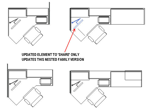
NOTE: Schematic TI content often has convenient parameters to allow maximum flexibility from a single family (manufacture specific content will never be this flexible). Create new types in your project if a variety of sizes are needed.

    Schedule Workstation Counts:
    Create Schedules for each layout Option, and filter by the “Starts with..” prefix WORKST.
    Option Workstation Count

    Posted in Architecture, BIM/Revit | Tagged , , , , , | 4 Comments

    Why/When to use Shared Parameters

    Revit is an Object Oriented Database, using numeric ‘handles’ to track data fields, and associate them to individual elements, via category definition. This invisible ‘handle’ is more important than the name of the parameter itself in correctly consolidating information. Whenever a parameter needs to extend beyond a single project file, the parameter needs to be a Shared Parameter, from an external master list, in order to establish the same handle across files. This includes project/annotation, as well as project/project. In other words: If you want to tag it, or want to pass it on to another project and have it show up correctly in a schedule, it must be a Shared Parameter.

    The Shared Parameter master list:
    Each project can be linked to an office wide Shared Parameter list. The path is preset in the Template, but may need to be mapped if the file is started without the template, or is from an outside source (manufacturer doors/windows, for instance). Please coordinate with your office BIM Coordinator/Manager to create new Shared Parameters. Loose management of this list can be very frustrating to the project teams, believe me!
    ____________________________________________________________________________

    Example of using a shared parameter:
    I may need to establish a “% Recycled Material” parameter for my casework families. I will need to schedule this info to effectively manage it in a project file, and I may want to be able to use filters or tags to quickly identify what elements meet a threshold criteria. Here’s the repercussions of using a non-shared vs shared parameter:

    Limitations of using Non-Shared Parameters:
    I can create the parameter as a Project Parameter directly in the project, perhaps by creating a new parameter in the casework schedule. I can now add the data from the manufacturer to the object easily. BUT – I can’t pass this family to another project and have it hold that data. Without a Shared Parameter, the family only has the data in the project environment. Once out of the project, that data field does not exist. I also cannot tag the casework with a custom tag that reports the data.

    Benefits of using Shared Parameters:

    Versatility and Consistency:
    a) OFFICE-WIDE DATA: Load that parameter into both the casework family itself, and into a custom casework tag. Also load it into the project environment. Because they (family, tag, project) all received the parameter from a single source, they data knows that it is the same ‘bit’ of information. Because the family holds that data, I can load it into another project and the value stays with the object.
    b) PROJECT SPECIFIC DATA: I can skip loading the shared parameter into the family, and only load it into the tag and the project environment. Saves me some time, and since my family represents a generic piece of casework, I don’t want that info to be permanently assigned to it, only assigned in the project. But using Shared Parameters gives me coordination through the custom tag, which can be a great efficiency tool when I want to quickly check the data across many instances of varied casework.

    Posted in BIM/Revit | Tagged , , , , | 1 Comment

    Converting CAD Details

    Every firm needs to invest time in converting their detail library from legacy CAD format into smart, editable Revit details. This is NOT a ‘push the EASY button’ process, but there are different methods with different (in value and future useability) results. Let your project’s budget and scheduling timeline guide your (immediate) decision process (but vow to ‘clean it up’ later!).

    Background: I recommend firms to set up a STANDARD DETAILS resource file (.rvt). Whereas CAD details are typically individual files in a library folder on the network, Revit details are Drafting Views in a project environment. Create Drafting View types to organize details, and implement naming standards. I use the desired sheet sequence as part of the naming convention, which makes it much easier to locate details from the resource file when transferring into projects (I remove the sheet number from the Title Used on Sheet).

    BEST PRACTICE – Cleanly Convert Individual Details:
    Open the CAD detail in Autocad adjacent Revit. Work in 2 Revit environments at the same time: the [FIRM] Standard Details.rvt file (located in the [FIRM] Content library in [FIRM] Templates folder) and a new Detail Component .rfa file.

    DraftingViewTypesa) Start a new drafting view in the [FIRM] Standard Details.rvt. Set the Drafting View TYPE to reflect the section/sheet this detail is destined for (this aids finding it for use in future projects). Link the CAD detail into the drafting view. Redo the text leaders with Revit Text Leaders (leave the dims for later, as you’ll need Revit objects created/placed first)

    b) Identify elements in the CAD detail that would be beneficial as a whole assembly – ie: sink section, etc. Isolate those lines and WBLOCK it to your desktop or other temporary space. This helps to reduce the amount of linework/style ‘clutter’ that working with the entire CAD detail brings in.

    c) Insert the WBLOCK .dwg into the Detail Component family. Use lines to pick the CAD linework, or if complexity/time is an issue, explode the WBLOCK. (at least you’ve minimized damage by WBLOCKing in the first place). If exploding, select linestyles (which will have CAD layer names) and change them out for the [FIRM] lines (1,1-HIDDEN, 3, 5 most common. DO NOT SKIP THIS STEP.)

    d) Save the Detail Component to the [FIRM] Library, [FIRM] Detail Components folder. Use intelligent naming, please. Also load into the [FIRM] Standard Details.rvt, and place in both the (visual library) DETAIL COMPONENTS view the new (detail) drafting view. BONUS: Not only does this convert the current detail, but becomes the resource for quickly creating new fully Revit details in the future.

    SelectDetailComponents
    e) Add standard detail elements (gypbd, metal studs, blocking, etc) from detail components found in the DETAIL COMPONENTS view (see browser). THIS SAVES A TON OF TIME. You can visually select what you need, then quickly RC > Create Similar, then go back to your detail and immediate place the desired element. No need to learn the precise name of all these very frequently used components – just look, select, Create Similar, and start detailing!

    f) Once detail components are in place, MOVE the CAD background off to the side. Then dimension to match the original detail (moving the CAD ensures you don’t dimension to CAD lines, which would then disappear once the CAD is removed).

    g) UNLOAD the CAD detail. Just deleting it from the view may keep confusing reference to it showing up in the Manage Links panel.

    NOW, GO FORTH AND CONVERT!

    ———————————————————————————————————–
    DISCLAIMER: THE FOLLOWING METHOD IS NOT RECOMMENDED AS A BEST PRACTICE, BUT CAN BE USED IN A DEADLINE SITUATION:
    ———————————————————————————————————–

    POOR DETAILING METHOD – Direct Use of CAD Details.

    a) Create a new drafting view in your project file. Link in the desired CAD detail.
    b) Recreate all Text and Dims (to match font/graphics of the Revit file)
    c) Select the CAD file, use QUERY, and select the layers for the CAD text leaders/dimensions and Hide In View.
    d) Accept that your detail cannot be modified or effectively edited, that linestyles and weights will not match other Revit details. Also, the project file archive risks broken links and lost relationship to any/all CAD based details.
    e) Vow to come back after the project deadline and rework the detail using the best practice method listed above.
    f) Keep your vow.

    Posted in BIM/Revit | Tagged , , , , , | 1,127 Comments

    Points on Point Clouds

    Having had the past pleasure (uhem) of working with client-provided point clouds, I was excited to view the AU2012 session on ‘Scan to BIM: Point Clouds Reloaded” presented by Kelly Cone of Beck Group. While a handout will never be as informative as a live presentation in terms of the ‘I get it now’ factor, I did find good validation of my past experience, and good tips on ensuring manageability for future PC projects:

    a) For any project bigger than a breadbox, coordination PRIOR to cloud collection is CRITICAL. My past experience? A dozen clouds randomly captured, with no coordinated reference point. Imagine the time, effort (and tears!) required to GUESS at how those collections should come together. (PS. methodical cloud capture flow and naming conventions would really help, too.)

    b) Use specialized tools. Cone’s session cites 2 options for Revit Add-Ons: Scan to BIM and CloudWorx.  Revit 2012 and on will natively import a cloud without these tools, but good luck with interpreting and efficiently creating elements without one of these (or possibly others) tools.

    c) Cull the noise. Unless you’re lucky enough to get scans of a completely vacant building, there’s going to be extraneous stuff in the way.  You can attempt to clear these away manually, but its faster and more accurate to use the specialized tools. Use a cloud viewer to validate your culling before you even begin to attempt geometry creation.

    d) Model large to small. Focus on your main elements – floor surface, reference wall plane. Make an educated guess (guesswork is still part of the equation) and let the tools seek out spatial relationships between your selections.  Model 3-4 major elements and re-evaluate the placement/orientation of the cloud positioning. As Kelly elegantly phrases:

      • A scan isn’t perfect and neither is reality, so don’t plan on matching it up perfectly. Use the “law” of averages to your advantage. (Everything will be close, but nothing will be perfect)

    The presentation certainly covers much more ground, and far further in depth, but these key points were what I wish I knew a year ago, and could have strategized before the project clock began ticking.


    Posted in BIM/Revit | Tagged , , , | 1 Comment

    Protected: Revit Resource Files

    This content is password protected. To view it please enter your password below:

    Posted in BIM/Revit | Tagged , , , | Comments Off on Protected: Revit Resource Files

    Guiding a model team

    I’m often doing ‘forensic analysis’ on project files – either for new clients, or in some cases, reviewing past project files before an upcoming new scope of work.  A primary aspect of reviewing models is not just finding issues, but communicating to the team the following:
    a) What the issue is
    b) Why it’s an issue (what’s the downside/repercussions, etc)
    c) What is the recommended approach (if one of several options, why this particular method)

    I use snapshots of the model as the primary means of identifying the issue, and write up a summary to accompany it. This is usually distributed to the entire office as a ‘Revit Revelation’* so it can be a learning opportunity for all project teams, not just the one who needs to resolve it.  These are also documented for future reference.

    This kind of training approach does require that an office be willing to have their errors (or just less-strategic decisions) aired to the rest of the team(s).  It should not be seen as finger-pointing, but as a directly applicable learning opportunity – the kind that really stick!  Another great benefit? The model snapshots give a visual clue as to how to conduct similar QA/QC checks on project models on their own.

    More power to the team!


    *That is SOOO trademarked, my fellow Revit bloggers!  ;^D

    Posted in BIM/Revit | Tagged , , , | 2 Comments